Equipment and Procedure
List of Components
- DM542T Digital Stepper Driver
- Arduino Uno
- Bread Board
- HX711 Amplifier
- Nema 17 Stepper Motor
- Load Cell
- 24V Power Supply
Circuit Diagram
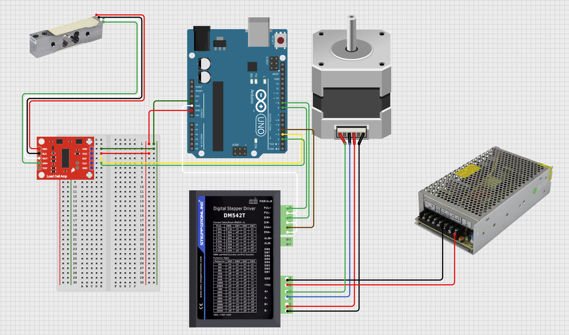
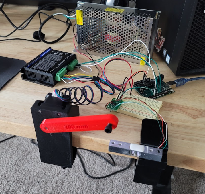
Electrical Assembly
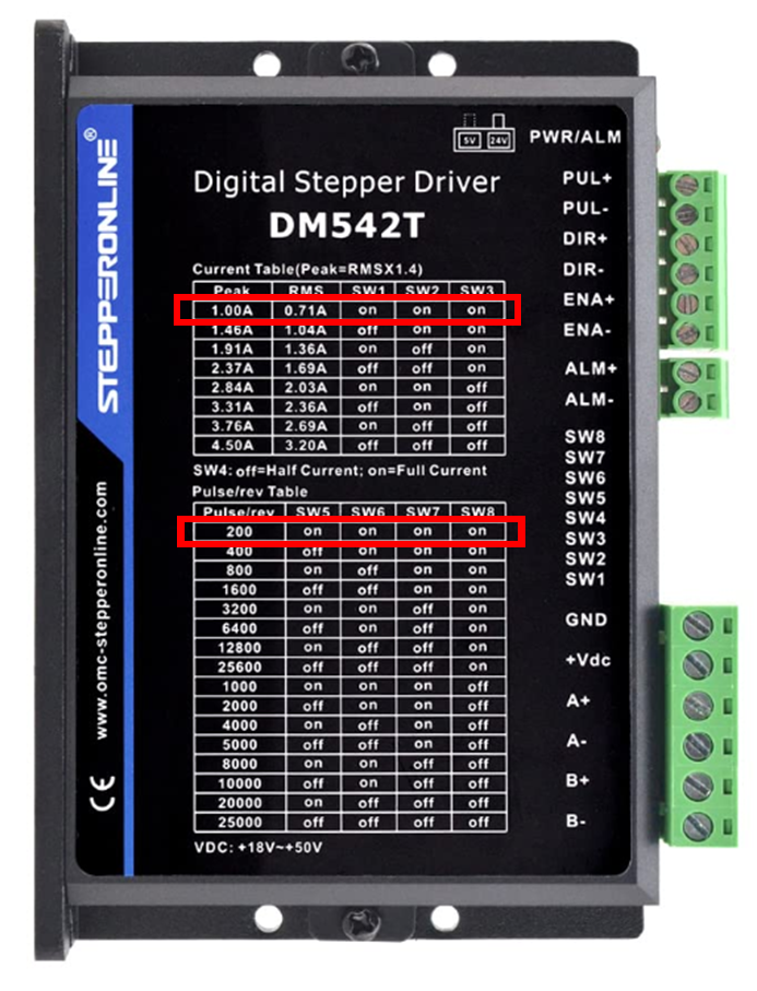
Follow the electrical schematic created during the planning phase of this project. Review motor driver documents to ensure that correct settings are made for their respective components. Nema 17 stepper motor has 1.8-degree steps, which means that a full revolution should experience 200 steps or pulses from the motor driver. The stepper motor also operates at a maximum of 1.5 Amps.
According to StepperOnline, the Nema 17 Stepper Motor's Black and Blue Leads correspond to the A +/- winding, while Green and Red represent B +/-. To ensure accuracy, it's recommended to test the continuity between these wires by measuring
the resistance of each paired lead. Once you have verified the connections, wire the motor driver accordingly.
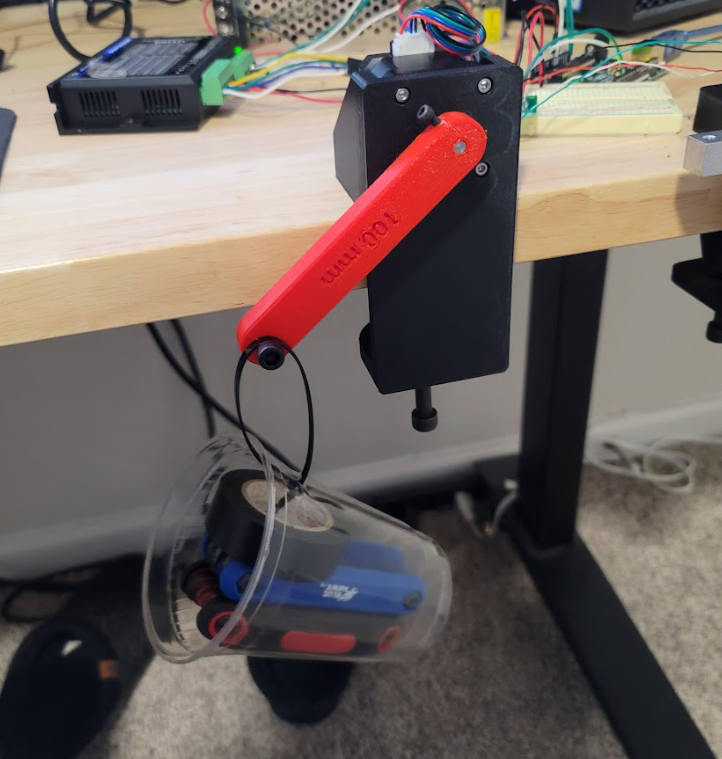
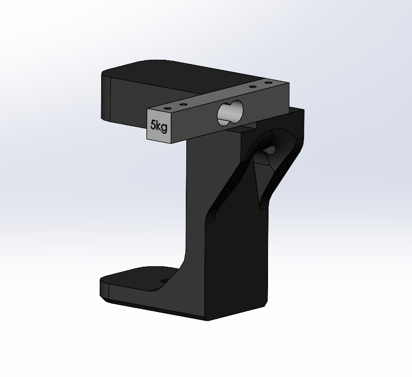
Load Cell Mount Design
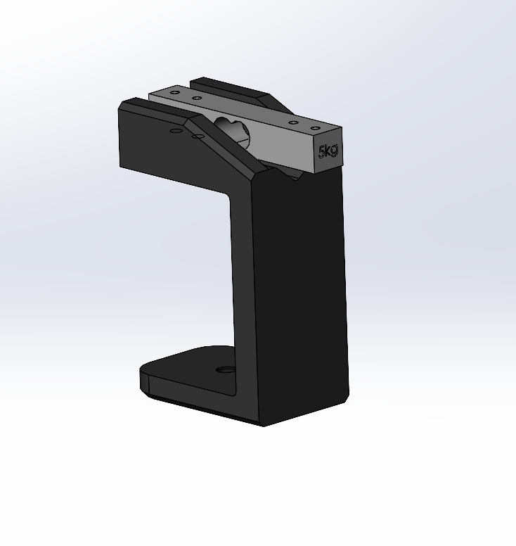
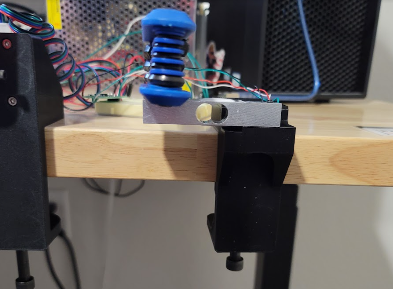
My intention was to design a mount that would position the load cell such that the incoming force of the stepper motor arm was perpendicular to the surface of the cell. Later found issues with this configuration for a few reasons.
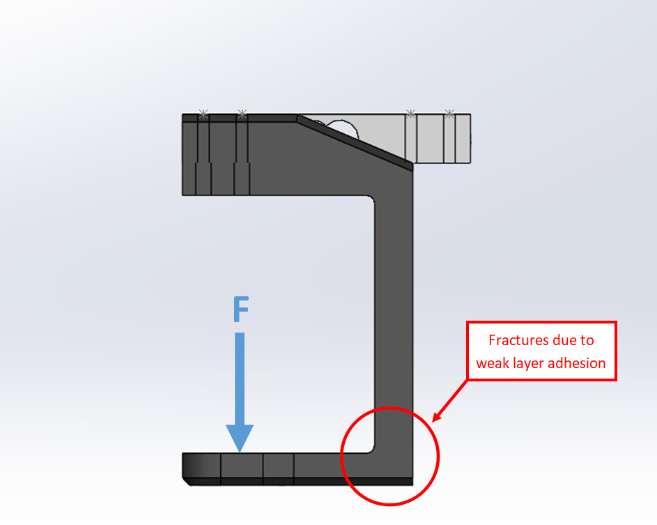
Based on where the loadcell was mounted (the left side of the below image), applied force from the arm was creating an additional moment about the right side member of the part, which was already experiencing forces from the clamp.
In addition to this, the part was printed in an orientation that supplied weak layer adhesion against the moment forces from both the clamp and the motor. The load cell was also mounted where the cell and the base of the mount
were both threaded. This prevented the screw from compressing the part to the base, missing out on additional overall stiffness.
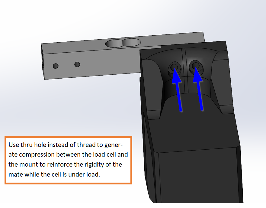
Improvements:
- Have a thru hole for the M4 mounting bolts to compress the part to the mount.
- Re-orient the part so that the layers are parallel to the applied force.
- Rotate the loadcell 90 degrees such that it is parallel to the motor arm to reduce the bending moment applied to the mount.
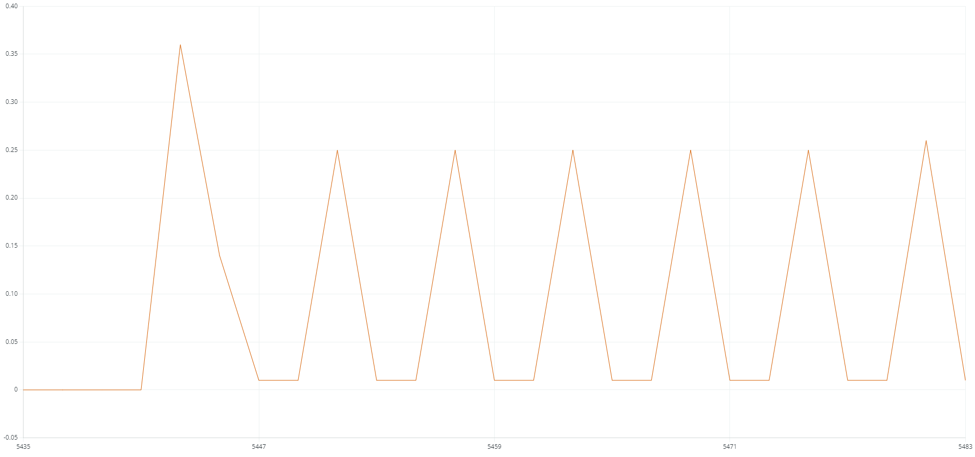
Load Cell Setup
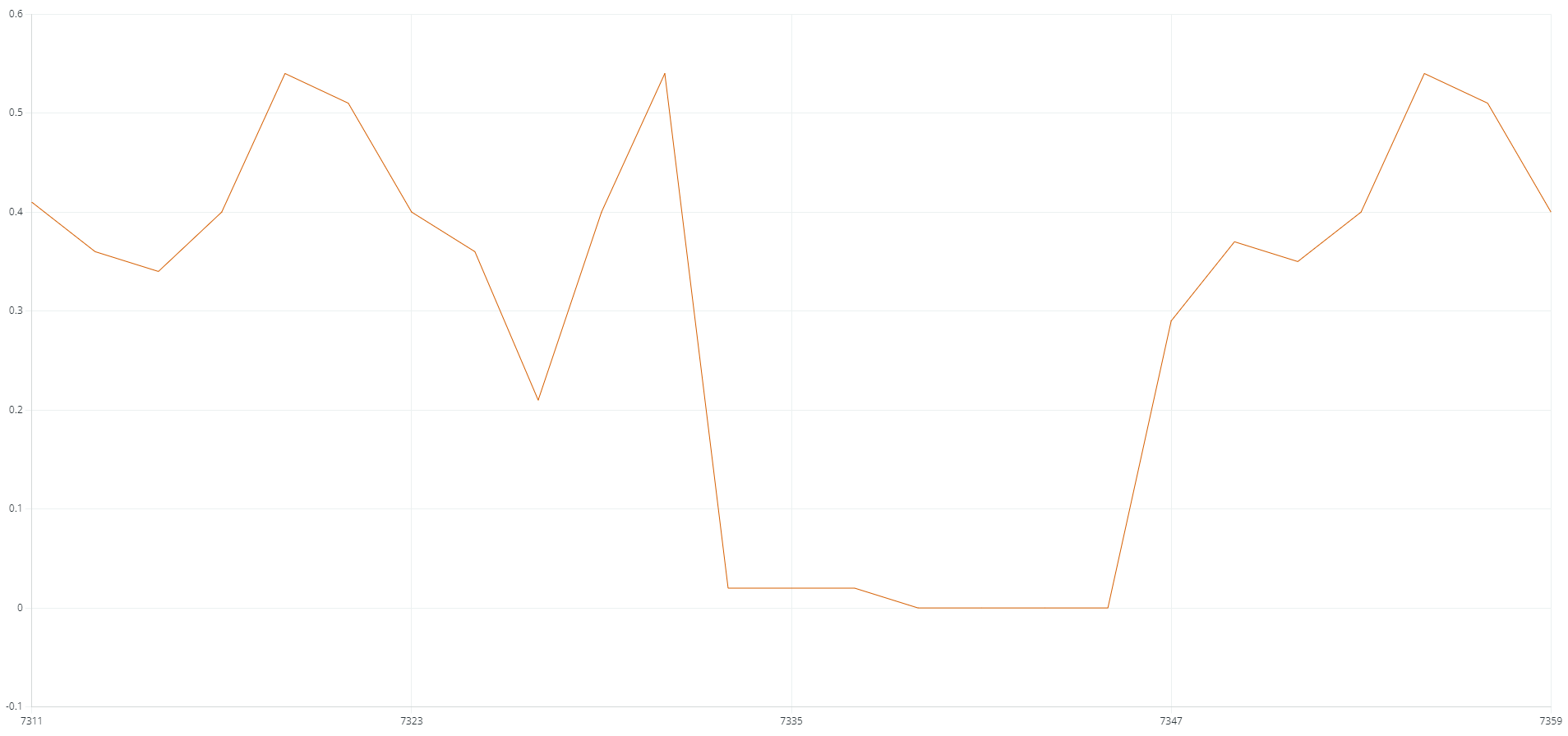
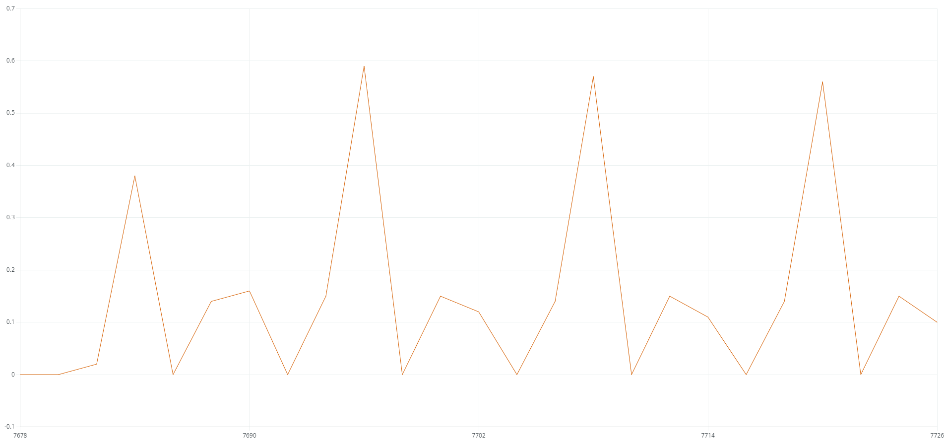
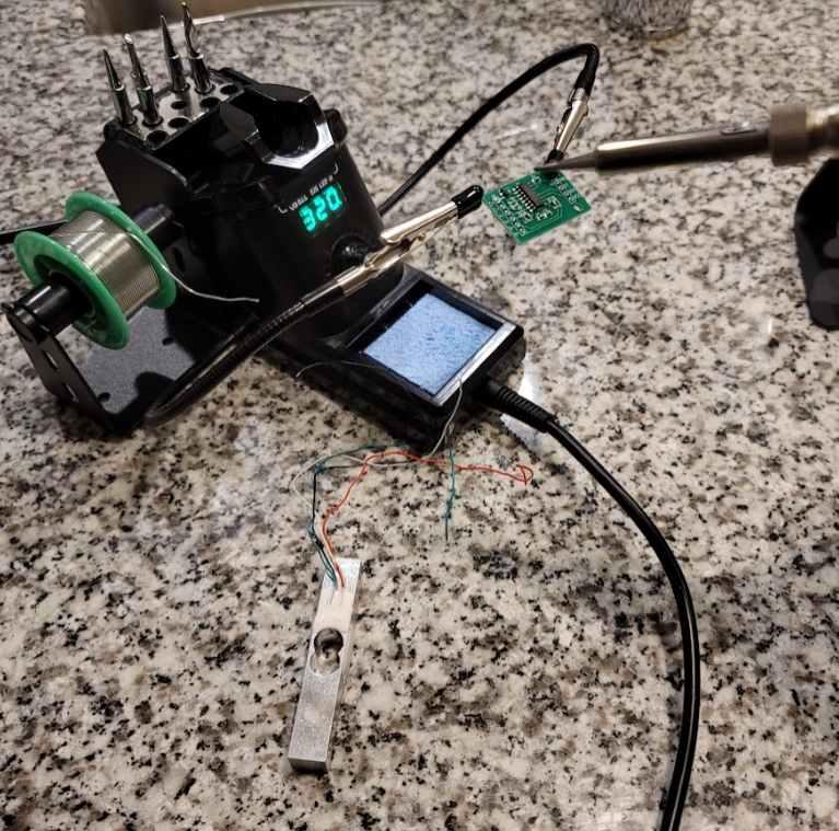
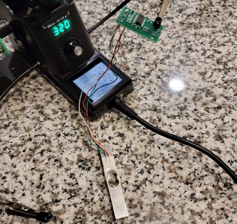
Setting up the load cell to measure force feedback from the motor arm. After wiring the components and running the test program, noticed that I was receiving inconsistent values with zero load.
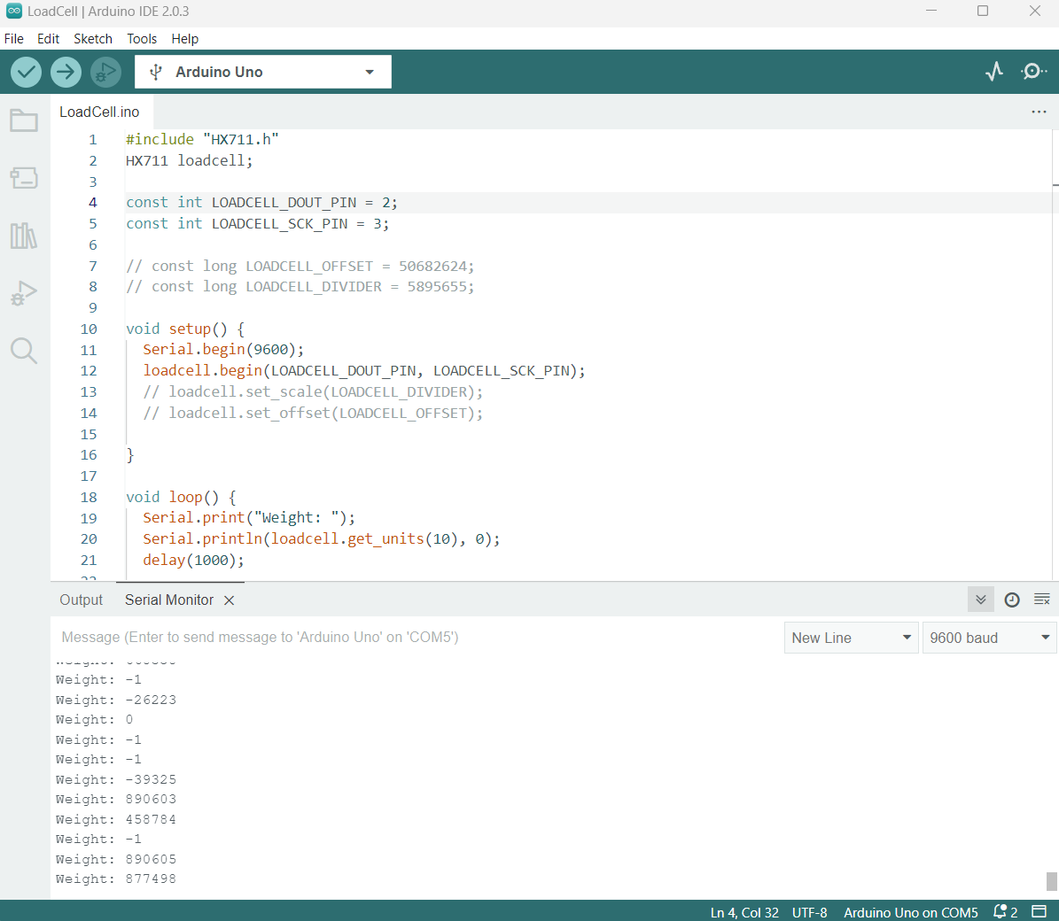
This could have been a calibration issue since that procedure was not completed, but it was also likely due to discontinuity between the cell and the amplifier. I did not have a solder, so ordered one to ensure proper contact between
the PCB and wires.
Load Cell Calibration
Used the following open-source program for load cell calibration.
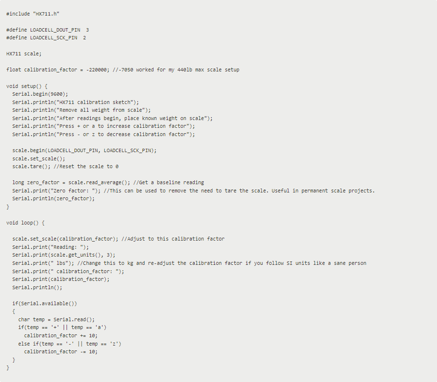
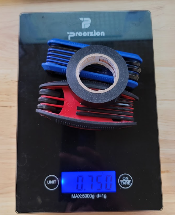
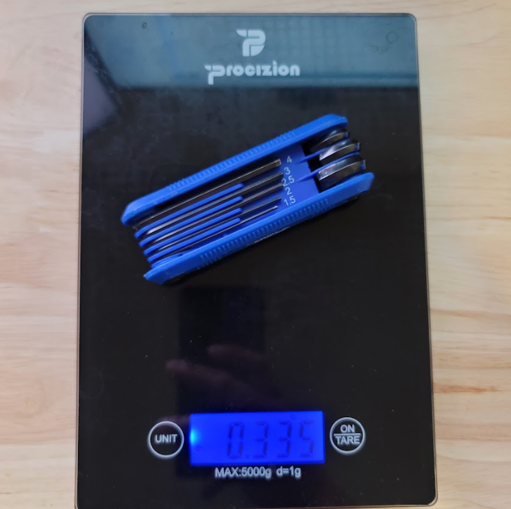
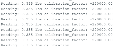
Measured the weight of a known object to use as my baseline for calibration. Placed the object on the load cell and adjusted the offset parameter until the load cell displayed the correct weight. offset was adjusted from -7050 to -220000.
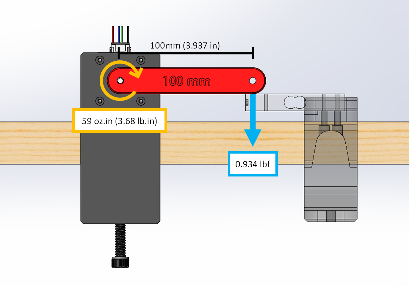
Calculations
The NEMA 17 motor has a maximum holding torque of 0.41 Nm or 3.68 lb-in. This means that the motor should be able to hold a weight of 3.68 lbs one inch from its axis of rotation. The below calculation shows how much force would be
applied from the arm if it were displaced by 3.937 in.